Juniper JN0-480 - Questions & Answers
Free preview · every answer includes a full explanation
Product page: https://prepkeys.com/jn0-480.html
Which statement is correct about making changes to a predefined device profile in Juniper Apstra?
The changes you make to a predefined device profile will be discarded and overwritten when upgrading the Apstra server version.
The processor load on the Apstra server will be negatively impacted when changes are made to a predefined device profile.
Changing the predefined device profile will also affect deployed devices that use the same profile.
You must reboot the Apstra server after changes are made to a predefined device profile before they will become active.
According to the Juniper documentation1, a predefined device profile is a configuration template that is shipped with Apstra software and supports most qualified Juniper devices. A predefined device profile cannot be changed, since any changes would be discarded and overwritten when you upgrade the Apstra server version. If you want to customize a predefined device profile, you can clone and edit it instead.
Therefore, the correct answer is A. The changes you make to a predefined device profile will be discarded and overwritten when upgrading the Apstra server version.
References:
Edit Device Profile | Apstra 4.2 |
Juniper Networks
In the Juniper Apstra Ul. you are creating a VNI pool for virtual networks.
In this scenario, which VNI range is acceptable?
Any range is acceptable for the VNI pool.
The valid VNI range is 4096 through 16777214.
The valid VNI range is 2 through 4096.
The valid VNI range is 1 through 10000.
In the Juniper Apstra UI, you can create VNI pools for virtual networks that use VXLAN encapsulation in the overlay network. A VNI pool is a resource pool that contains a range of VNIs that can be assigned to the virtual networks. The valid VNI range for a VNI pool is 4096 through 16777214, according to the VXLAN standard 1. Therefore, the statement B is correct in this scenario.
The following three statements are incorrect in this scenario: Any range is acceptable for the VNI pool. This is not true, because the VNI range has a lower and upper limit defined by the VXLAN standard 1. The lower limit is 4096, and the upper limit is 16777214. Any VNI outside this range is invalid and cannot be used for VXLAN encapsulation.
The valid VNI range is 2 through 4096. This is not true, because the VNI range does not start from 2, but from 4096. The VNIs from 2 to 4095 are reserved and cannot be used for VXLAN encapsulation 1.
The valid VNI range is 1 through 10000. This is not true, because the VNI range does not include 1, which is also reserved and cannot be used for VXLAN encapsulation 1. The VNI range also does not end at 10000, but at 16777214, which is the maximum possible value for a 24-bit VNI field 1.
References:
VNI Pools (Resources)
Using Juniper Apstra.
which component is defined in a template?
the leaf-to-spine interconnection
the speed of the links between the spine devices and the leaf devices
the number of spine devices in a topology
the definition of IP pools
According to the Juniper documentation1, a template is a configuration template that defines a network's policy intent and structure. A template can be either rack-based or pod-based, depending on the type and number of racks and pods in the network design. A template includes the following details: Policies: These are the parameters that apply to the entire network, such as the overlay control protocol, the ASN allocation scheme, and the underlay type. Structure: This is the physical layout of the network, such as the type and number of racks, pods, spines, and leaves. The structure also defines the leaf-to-spine interconnection, which is the number and type of links between the leaf and spine devices. The leaf-to-spine interconnection can be either single or dual, depending on the redundancy and bandwidth requirements.
Therefore, the correct answer is A. the leaf-to-spine interconnection. This is a component that is defined in a template, as it determines the physical connectivity of the network. The speed of the links, the number of spine devices, and the definition of IP pools are not components that are defined in a template, as they are either derived from the device profiles, the resource pools, or the blueprint settings.
References:
Templates Introduction | Apstra 4.2 | Juniper Networks
When working with logical devices, you specify where each port group is connected.
In thisscenario, which two Juniper Apstra Ul options are available to the operator? {Choose two.)
router
unused
generic
firewall
When working with logical devices, you specify where each port group is connected by selecting the port group layout and the port speed and role (s) for each port group. The Juniper Apstra UI offers two options to the operator for the port group role: unused and generic.
Unused: This option means that the port group is not configured or used by Apstra. This can be useful for ports that are faulty, reserved, or not part of the data center fabric.
Generic: This option means that the port group is configured with a generic role that is not specific to any device type or function. This can be useful for ports that are used for testing, troubleshooting, or custom purposes.
References:
Logical Devices
Which attribute enables Juniper Apstra to scale and manage thousands of devices with a single server instance?
Apstra is installed as a cloud resource.
Apstra is based on NGINX.
Apstra is available as an OVA.
Apstra is a distributed state system.
The attribute that enables Juniper Apstra to scale and manage thousands of devices with a single server instance is that Apstra is a distributed state system. This means that Apstra uses a graph database to store the network topology and configuration data in a distributed and replicated manner across multiple server nodes. This allows Apstra to handle large-scale networks with high performance, reliability, and availability. Apstra also uses a stateful orchestration engine that ensures the network state is always consistent with the intent of the blueprint, which is the logical representation of thenetwork design and behavior. Apstra can automatically detect and resolve any discrepancies between the desired and actual network state, as well as handle any changes or failures in the network. The other options are incorrect because:
A. Apstra is installed as a cloud resource is wrong because Apstra can be installed either as a cloud
resource or as an on-premises resource. Apstra is available as a virtual machine image that can be deployed on various hypervisors, such as VMware ESXi, QEMU/KVM, Microsoft Hyper-V, or Oracle VirtualBox. Apstra can also be deployed on public cloud platforms, such as Amazon Web Services (AWS) or Microsoft Azure. However, the installation method does not affect the scalability of Apstra, which is determined by the distributed state system architecture.
B. Apstra is based on NGINX is wrong because Apstra is not based on NGINX, but on Python and Django. NGINX is a web server and reverse proxy that Apstra uses to serve the web user interface and the REST API. However, NGINX is not the core component of Apstra, and it does not affect the scalability of Apstra, which is determined by the distributed state system architecture.
C. Apstra is available as an OVA is wrong because Apstra is available as an OVF, not an OVA. An OVF (Open Virtualization Format) is a standard format for packaging and distributing virtual machine images. An OVA (Open Virtual Appliance) is a single file that contains the OVF and the virtual disk images. Apstra provides an OVF file that can be imported into various hypervisors, such as VMware ESXi, QEMU/KVM, Microsoft Hyper-V, or Oracle VirtualBox. However, the availability of Apstra as an OVF does not affect the scalability of Apstra, which is determined by the distributed state system architecture.
References:
JUNIPER APSTRA ARCHITECTURE
Apstra Server Requirements/References
Juniper Networks Apstra 4.0 enhances the experience of users and operators
Using the Juniper Apstra multitenancy capabilities, which approach will allow a tenant to interconnect two different routing zones?
Interconnection is the default behavior.
Use interconnection through the fabric spine nodes.
Interconnection cannot be enabled.
Use interconnection through an external gateway.
According to the Juniper documentation, a routing zone is an L3 domain, the unit of tenancy in multi-tenant networks. You create routing zones for tenants to isolate their IP traffic from one another, thus enabling tenants to re-use IP subnets. In addition to being in its own VRF, each routing zone can be assigned its own DHCP relay server and external system connections. You can create one or more virtual networks within a routing zone, which means a tenant can stretch its L2 applications across multiple racks within its routing zone. For virtual networks with Layer 3 SVI, the SVI is associated with a Virtual Routing and Forwarding (VRF) instance for each routing zone isolating the virtual network SVI from other virtual network SVIs in other routing zones. If you're using multiple routing zones, external system connections must be from leaf switches in the fabric. Routing between routing zones must be accomplished with external systems. Therefore, the correct answer is D. Use interconnection through an external gateway.
References:
Routing Zones
You are receiving cable, interface, and BGP anomalies from several devices within the data center fabric.
In Juniper Apstra.
how would you troubleshoot these types of errors?
In the Ul, go to Time Voyager and revert to the last working version.
In the Ul, access the console to the devices and review the interface states.
In the Ul, go to Devices and confirm that agent connectivity is fine.
In the Ul, verify device connectivity by consulting the cable map.
The cable map is a graphical representation of the physical connections between the devices in the data center fabric. It shows the status of the cables, interfaces, and BGP sessions for each device. You can use the cable map to identify and troubleshoot any cable, interface, or BGP anomalies that may occur in the fabric. You can also filter the cable map by device name, device type, device role, device state, cable state, interface state, or BGP state.
References:
Cable Map Overview
Cable Map User Guide
Which two statements are correct about repairing a Juniper Apstra cabling map before deploying your blueprint? (Choose two.)
You must manually change the cabling map to update spine-to-leaf fabric links.
Apstra can use LLDP data from the spine-to-lea! fabric devices to update the connections in the cabling map.
Apstra can use LLDP data from the leaf devices to update the leaf-to-generic connections in the cabling map.
You must manually change the cabling map to update leaf-to-generic links.
The cabling map is a graphical representation of the physical connections between the devices in the data center fabric. It shows the status of the cables, interfaces, and BGP sessions for each device. You can use the cabling map to verify and repair the cabling before deploying your blueprint. Based on the web search results, we can infer the following statements: Apstra can use LLDP data from the spine-to-leaf fabric devices to update the connections in the cabling map. This is true because Apstra can collect LLDP data from the devices using the Generic Graph Collector processor and use it to update the cabling map automatically. LLDP is a protocol that allows devices to exchange information about their identity, capabilities, and neighbors. Apstra can use LLDP data from the leaf devices to update the leaf-to-generic connections in the cabling map. This is true because Apstra can also collect LLDP data from the leaf devices and use it to update the connections to the generic devices, such as routers, firewalls, or servers. Generic devices are devices that are not managed by Apstra but are part of the data center fabric. You must manually change the cabling map to update spine-to-leaf fabric links. This is false because Apstra can use LLDP data to update the spine-to-leaf fabric links automatically, as explained above. However, you can also manually change the cabling map to override the Apstra-generated cabling, if needed 24. You must manually change the cabling map to update leaf-to-generic links. This is false because Apstra can use LLDP data to update the leaf-to-generic links automatically, as explained above. However, you can also manually change the cabling map to override the Apstra-generated cabling, if needed.
References:
LLDP Overview
Edit Cabling Map (Datacenter)
Generic Devices
Import / Export Cabling Map (Datacenter)
Exhibit.
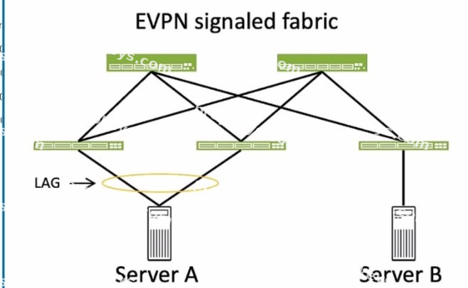
Which two statements about ESI values are correct for the server connections to the fabric shown in the exhibit? (Choose two.)
A valid ESI value for Server A is 0x00.00.00.00.00.00.00.00.00.00.
A valid ESI value for Server B is 0x00.20.20.20.20.20.20.20.20.20.
A valid ESI value for Server A is 0x00.10.10.10.10.10.10.10.10.10.
A valid ESI value for Server B is 0x00.00.00.00.00.00.00.00.00.00.
To answer this question, we need to understand the concept of ESI values in EVPN LAGs. An ESI is a 10- byte value that identifies an Ethernet segment, which is a set of links that connect a multihomed device (such as a server) to one or more PE devices (such as leaf switches) in an EVPN network. The same ESI value must be configured on all the PE devices that connect to the same Ethernet segment. This allows the PE devices to form an EVPN LAG, which supports active-active or active-standby multihoming for the device. The ESI value can be manually configured (type 0) or automatically derived from LACP (type 1) or other methods. In the exhibit, Server A is connected to two leaf switches (QFX 5210) using a LAG with LACP enabled. Server B is connected to three leaf switches (QFX 5120) using a LAG with LACP enabled.
Based on this information, the following statements are correct about ESI values for the server connections to the fabric: A valid ESI value for Server A is 0x00.10.10.10.10.10.10.10.10.10. This is true because this ESI value can be automatically derived from the LACP configuration on the QFX 5210 devices. The LACP system ID is usually based on the MAC address of the device, and the LACP administrative key is a 2-byte value that identifies the LAG. For example, if the MAC address of the QFX 5210 device is 00:10:10:10:10:10 and the LAG ID is 10, then the LACP system ID is 00:10:10:10:10:10 and the LACP administrative key is 00:0A. The ESI value is then derived by concatenating the LACP system ID and the LACP administrative key, resulting in 00:10:10:10:10:10:00:0A.
This ESI value can be represented in hexadecimal notation as 0x00.10.10.10.10.10.00.0A, or padded with zeros as 0x00.10.10.10.10.10.00.0A.00.00. This ESI value must be configured on both QFX 5210 devices that connect to Server A.
A valid ESI value for Server B is 0x00.00.00.00.00.00.00.00.00.00. This is true because this ESI value is a reserved value that indicates a single-homed device. Server B is connected to three leaf switches (QFX
5120) using a LAG, but it is not multihomed to any of them. This means that Server B does not need an ESI value to form an EVPN LAG with any of the leaf switches. Instead, Server B can use the reserved ESI value of 0x00.00.00.00.00.00.00.00.00.00, which indicates that it is a single-homed device and does not participate in any EVPN LAG. This ESI value must be configured on all three QFX 5120 devices that connect to Server B. Thefollowing statements are incorrect about ESI values for the server connections to the fabric: A valid ESI value for Server A is 0x00.00.00.00.00.00.00.00.00.00. This is false because this ESI value is a reserved value that indicates a single-homed device. Server A is connected to two leaf switches (QFX
5210) using a LAG with LACP enabled, which means that it is multihomed to both of them. This means that Server A needs an ESI value to form an EVPN LAG with the leaf switches. The ESI value must be unique and non-zero for each Ethernet segment, so the reserved ESI value of 0x00.00.00.00.00.00.00.00.00.00 is not valid for Server A.
B. A valid ESI value for Server B is 0x00.20.20.20.20.20.20.20.20.20. This is false because this ESI value is not derived from the LACP configuration on the QFX 5120 devices. Server B is connected to three leaf switches (QFX 5120) using a LAG with LACP enabled, but it is not multihomed to any of them. This means that Server B does not need an ESI value to form an EVPN LAG with any of the leaf switches. Instead, Server B can use the reserved ESI value of 0x00.00.00.00.00.00.00.00.00.00, which indicates that it is a single-homed device and does not participate in any EVPN LAG. The ESI value of 0x00.20.20.20.20.20.20.20.20.20 is not valid for Server B, and it may cause conflicts with other Ethernet segments that use the same ESI value.
References:
Ethernet Segment Identifiers, ESI Types, and LACP in EVPN LAGs Understanding Automatically Generated ESIs in EVPN Networks Ethernet Segment in EVPN: All You Need to Know
Exhibit.
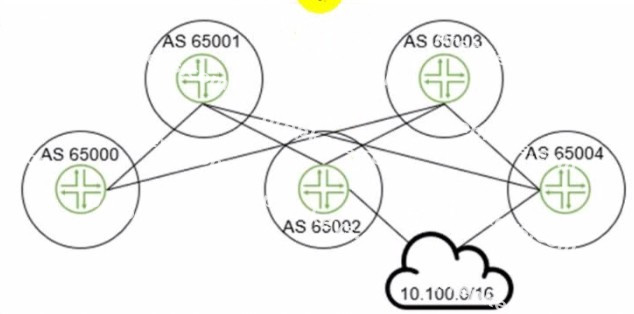
The 10.100.0.0/16 route is being advertised into your BGP IP fabric.
ECMP load balancing has been properly enabled on all devices In this scenario, how many routes will the leaf device in AS 65000 receive for the 10.100.0.0/16 prefix?
3
1
2
4
The leaf device in AS 65000 will receive three routes for the 10.100.0.0/16 prefix, one from each spine device in AS 65001, AS 65002, and AS 65003. Since ECMP load balancing is enabled, the leaf device will install all three routes in its routing table and distribute the traffic among them. The other options are incorrect because: 1 is wrong because the leaf device will not receive only one route for the prefix. It will receive multiple routes from different spine devices and use ECMP to load balance among them. 2 is wrong because the leaf device will not receive only two routes for the prefix. It will receive three routes from three spine devices, as explained above. D. 4 is wrong because the leaf device will not receive four routes for the prefix. It will receive three routes from three spine devices, as explained above. The fourth spine device in AS 65004 is not directly connected to the leaf device and will not advertise the prefix to it.
References:
IP Fabric Underlay Network Design and Implementation BGP Multipath load sharing iBGP and eBGP ECMP Load Balancing
Showing 10 of 65 questions · Unlock the full set